Structural detailed solution of shell and tube heat exchanger
- Wilson Pipeline
- Jan 5, 2022
- 8 min read
Structural detailed solution of shell and tube heat exchanger
The shell-and-tube heat exchangers mainly include structural types such as fixed tube-plate heat exchangers, floating-head heat exchangers, U-tube heat exchangers, and packing-type floating-head heat exchangers. The structure of the fixed-tube heat exchanger is simple. The low manufacturing cost can obtain a smaller shell inner diameter. The tube process can be pided into multiple types. The shell process can also be pided into multiple passes by longitudinal partitions. The advantages such as wide range of specifications are widely used in the project. Today, we took everyone together to take the structure of the fixed tube-plate heat exchanger as an example to understand the structure of the shell-and-tube heat exchanger.

Fixed tube heat exchanger.
Structure diagram of fixed tube plate heat exchanger
Tube box
Pipe box structure


The common pipe box structure can be roughly pided into the following categories, as shown above.
A-type pipe box can be used for single pipe and multiple pipe runs. The advantage is that it is easy to clean the tube of the heat exchanger; the disadvantage is that there are many materials for the pipe cover structure. When the size is large, it needs forgings, so it is recommended that the A-type tube box Suitable for DN ≤ 900mm.
B-type pipe box is used for single pipe and multiple pipe, the advantage is that the structure is simple, easy to manufacture; the disadvantage is that when the inspection and cleaning tube heat exchange tube, the pipe flange on the pipe and the equipment flange need to be disassembled And remove the overall tube box.
C-type pipe box The pipe box is the return pipe box of a multi-tube heat exchanger.
D-type pipe box The pipe box is used for the inlet and outlet of a single-tube heat exchanger.
The flat cover of the pipe box is an important part of the pipe box. Different flat covers can be selected according to the use, material cost, and convenience of cleaning.
Pipe box flat cover structure as shown
a) Figure 1 shows the overall structure of the tube box cover, mainly used when the tube box is carbon steel or low alloy steel material.

Figure 1 Tube cover of the overall structure
b) Figure 2 shows the lid of the composite structure for the case of stainless steel or corrosion-resistant alloys.

Figure 2 Composite tank cap
c) Figure 3 shows the lid of the tank cap welded with a lining plate, but it is not suitable for applications in a vacuum state.

Fig. 3 Casing plug cap welding
The effective thickness of the overall structure of the pipe box cover should be equal to the actual thickness of the pipe box cover minus the corrosion margin of the pipe box or the corrosion margin of the pipe box and the large value of the partition plate groove depth. For composite tank caps and liner tank caps, the composite or liner thickness is not included in the effective thickness.
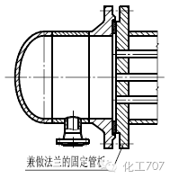
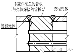
According to the connection structure between the tube sheet, the tube box and the shell, the tube sheet can be pided into:
a) The extension part doubles as a fixed tube plate for the flange.
b) Fixed tube plates that do not double as flanges and that are welded together with shell and tube barrels.
As shown below:


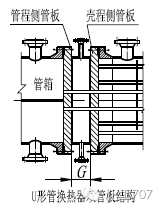
According to the use function (use) of the tube sheet, the tube sheet is pided into:
a) Fixed tubesheets for fixed tubesheet heat exchangers;
b) Fixed tube plates and floating tube plates of floating head heat exchangers;
c) fixed tube plates of U-tube heat exchangers;
d) Double tube sheet heat exchanger double tube plate;
e) Thin tube sheet.


In the fixed tube plate heat exchanger, in order to avoid the tensile failure of the shell and the heat exchange tube, the heat exchange tube is unstable, and the heat exchange tube is pulled off from the tube plate. Therefore, a flexible compensating element must be provided in the middle of the housing. – Expansion joints to reduce the axial load of the shell and the heat transfer tubes, and to reduce the stress of the tube sheet caused by the difference in thermal expansion, thereby appropriately thinning the thickness of the tube sheet.
Type of expansion joint for heat exchanger
There are many types of expansion joints. According to the cross-sectional shape, there are U-shaped, Ω-shaped, and S-shaped. In the fixed tube-plate heat exchanger, the U-shaped wave expansion joint is the most common and most common.
U-shaped expansion joints are mainly composed of two parts: a corrugated tube and a straight edge section. If necessary, liners may be provided to reinforce the ring, as shown in the figure:

Expansion joints for heat exchangers can also be pided into single-layer and multi-layer expansion joints.
a) For fixed tube sheet heat exchangers, under the premise of ensuring the bearing capacity required by the design and compensating stiffness and fatigue life, single-layer wave expansion joints should be preferred.
b) In the following cases, multi-layer waveform expansion joints can be used
1) Must withstand higher pressures and require greater displacement compensation capability;
2) requirements to withstand higher fatigue life;
The features of the multi-layered waveform expansion joint structure are as follows:
1) Good flexibility and high compensation capability;
2) Fatigue life is higher than single-layer structure (foreign data is 6 times that of single layer);
3) Compact structure, saving material;
4) In the case of high pressure, it will not burst suddenly and it is not easy to be dangerous.
The heat exchange tube is the core part of the heat exchanger. Different diameters, shapes, and arrangements of heat exchange tubes will affect the efficiency of the heat exchanger.
Pipe diameter
The recommended lengths of the heat transfer tubes are 1.5, 2.0, 2.5, 3.0, 4.5, 6.0, 7.5, 9.0, 12.0m.
Common specifications of heat exchange tubes are shown in Table 1 below
Table 1 Common specifications of heat exchange tubes

Shape
U-shaped heat exchange tube
The bend radius R (as shown in the figure below) of the U-tube bend section shall not be less than twice the outer diameter of the heat exchange tube. The minimum bend radius R min of the commonly used heat exchange tube shall be selected according to Table 2.

Table 2 Minimum bending radius of heat exchange tubes
Heat exchange tube outer diameter
10
14
19
25
32
38
45
57
R min
20
30
40
50
65
76
90
115
When the flow rate in the U-shaped tube is too high or there is corrosion, the wall thickness of the U-shaped tube with a small radius of the curved tube should be appropriately thickened.
Heat exchange tube arrangement
The heat exchanger tube standard arrangement form sees


a) Triangle arrangement
The triangular arrangement (including the arrangement of the regular triangles and the arrangement of the corner triangles) is the most common form of arrangement, particularly in fixed tube-plate heat exchangers where the shell-side medium is relatively clean and the heat exchange tubes do not need to be cleaned.
b) Square arrangement
The square arrangement is generally used in floating head heat exchangers and U-tube heat exchangers that need to be cleaned outside the heat exchange tubes.
c) Arrangement of regular triangles and squares of corners (see figs. a and d). It is called staggered on heat transfer, and turbulence can be formed when the medium flows, which is beneficial to heat transfer. The corner triangles and square arrays (see Figures b, c) are called in-line in terms of heat transfer. When the medium flows, part of it is laminar, which has an adverse effect on heat transfer.
Therefore, for heat exchangers with no phase transition, there is a large relationship between heat transfer and the flow state of the medium. Therefore, it is better to use a regular triangle or a corner square arrangement. For the condenser with phase change, because the relationship between the heat transfer and the flow of the medium is small, and only the relationship of the direction of the condensate flow in the pipe wall is relatively large, generally a corner triangle and a square arrangement can be used.
Shell structure
Common typical shell side components are shown in Table 3.
Table 3 Common typical shell side components
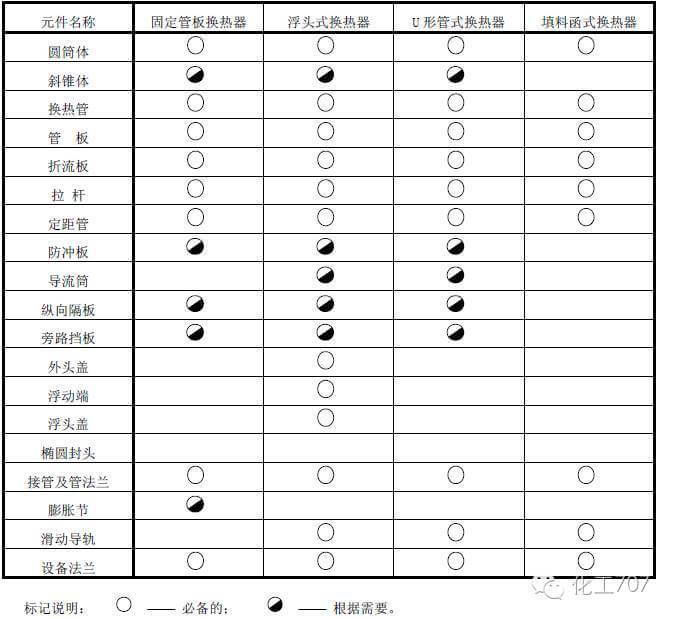
The role of baffles
a) Increase the flow rate of the medium between the shell side tubes to improve the heat transfer effect.
b) Support the heat exchange tubes.
c) Adjust the baffle spacing to play a role in avoiding tube bundle induced vibration.
Baffle shape
The commonly used baffle plates and support plates have two types of bow-shaped and disk-annular shapes. In addition, there are other types of baffles and supporting plates as required, such as rectangular hole circular plates and rectangular baffles, as shown in the figure:
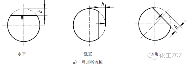


a) Single bow baffle (figure a): is the most commonly used form. Its form is simple, but the pressure drop is large.
1) Arranged up and down (horizontal incision) means that the material inlet and arcuate notch are vertically arranged to cause severe disturbance of the medium to increase the heat transfer coefficient.
2) Arranged in the right and left (vertical gap) means that the material inlet and the arcuate gap are arranged in parallel. Mostly used for horizontal condensers or evaporators to facilitate the flow of condensate and gases.
3) The corner arrangement is generally used for the square arrangement of the heat exchange tubes, which can form turbulence in the fluid to improve the heat transfer efficiency.
b) Double bow (figure b) and three bowed baffles (figure c): This applies to flows with a relatively large shell-side flow, or when the shell-side fluid is a low density, low pressure drop. The decrease in the heat transfer coefficient is much smaller; at the same time, this form is also conducive to preventing the vibration induced during the flow of the medium.
c) Disc – Circular annular baffle (Fig. d): The disc is arranged in a staggered arrangement with the ring. The media flow characteristics are symmetrical to the axis.
d) Rectangular baffles (figure e): The rectangular baffles can be placed horizontally or vertically, while the horizontal flow is generally used when the shell-side medium is in the gas phase, and the vertical flow is used for the shell-side medium in the liquid phase or with condensation. Liquid occasions. These two forms are usually used in large diameter and large flow conditions.
Pull rod and distance tube
The baffle plate and the support plate are generally fixed by tie rods or tie rods and distance tubes and tube plates. There are two commonly used fixed structures, namely the distance between the rod and the spot welding structure, as shown in the figure:


a) Tie rod distance tube structure, used for tube bundles with an outside diameter of the heat exchange tube greater than or equal to 19mm.
b) Rod and baffle spot welding structures for tube bundles with outer diameters less than or equal to 14mm.
1 Rod size
The tie rod connection dimensions are as shown in the figure and Table 4.

Table 4 Tie rod size

2 Rod arrangement
Pull rods should be arranged as evenly as possible on the outer edge of the tube bundle. For large diameter heat exchangers, a suitable number of tie rods should be placed in or near the baffle notch.
Double shell structure
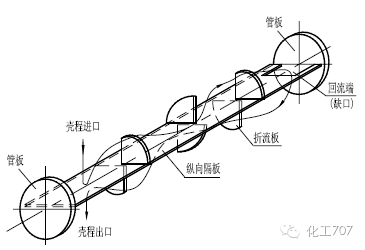
In the shell, a rectangular flat plate parallel to the axis of the heat exchange tube is installed, that is, a longitudinal partition, and the shell process is pided into two, that is, the double shell process, as shown in the figure. This structure can increase the flow rate of the shell material and improve the heat transfer effect, that is, increase the heat transfer coefficient. From the economic point of view, a double-shell heat exchanger is cheaper than two single-tube heat exchangers.
Today we mainly introduced the fixed tube-plate heat exchangers in shell-and-tube heat exchangers. Because many of the heat transfer parts and components are common, some of the parts and components that we do today are not very detailed, and we hope that users will work together to improve them. More parts structure.
Source: China Heat Exchanger Tubes Manufacturer – wilsonpipeline Pipe Industry Co., Limited (www.wilsonpipeline.com)

Comments