WILSON PIPLINE
Search Results
2112 results found with an empty search
- Introduction to pipes and the schedule terminology
For pipes of all dimensions the outside diameter (O.D.) remains relatively constant. The variation in wall thickness affects only the inside diameters (I.D.). A schedule number indicates the approximate value of Sch. = 1000 P/S where P = service pressure (psi) S = allowable stress (psi) The higher the schedule number is, the thicker the pipe is. Since the outside diameter of each pipe size is standardized, a particular nominal pipe size will have different inside pipe diameter depending on the schedule specified. Welded and Seamless Wrought Steel Pipes To distinguish different weights of pipe it is common to use the Schedule terminology from ANSI/ASME B36.10 Welded and Seamless Wrought Steel Pipe: Light Wall Schedule 10 (Sch/10, S/10) Schedule 20 (Sch/20, S/20) Schedule 30 (Sch/30, S/30) Schedule 40 (Sch/40, S/40) Standard Weight (ST, Std, STD) Schedule 60 (Sch/60, S/60) Extra Strong (Extra Heavy, EH, XH, XS) Schedule 80 (Sch/80, S/80) Schedule 100 (Sch/100, S/100) Schedule 120 (Sch/120, S/120) Schedule 140 (Sch/140, S/140) Schedule 160 (Sch/160, S/160) Double Extra Strong (Double extra heavy, XXH, XXS) Note that many of the schedules are identical in certain sizes. Stainless Steel Pipes For stainless steel pipes thru 12-inch schedule numbers from Schedule 5S to schedule 80S are used as published in ANSI/ASME 36.19M Stainless Steel Pipe. Schedule 5S (Sch/5S, S/5S) Schedule 10S (Sch/10S, S/10S) Schedule 40S (Sch/40S, S/40S) Schedule 80S (Sch/80S, S/80S)
- The basic method of weld metal of stainless steel flanges
When large diameter flange of the steel alloy 76 less, and are too many wire materials containing alloying elements, alloying elements to improve the weld function in these influence under the condition of a sticking point, add the function of fusion than will cause weld is reduced. Stainless steel flange weld metal melting of cross-sectional area of F the cross-sectional area of the filler metal mode to FH, weld the cross-sectional area of F – 4 FH, (F, 4 fj is weld seam of fusion than 7. Fusion than 7 basis will affect the chemical composition of weld, stainless steel flange organization and mechanical function. Fusion than can be all stainless steel flange metal in the weld of the proportion of intrusive, so when the chemical composition of welding wire and steel metal are large difference, stainless steel flange weld level affected by the composition of steel chemical composition is directly related to the fusion ratio. The greater the fusion ratio. Parent metal components, the greater the influence of weld. For example when non-standard flange metal than wire contains more impurities (such as carbon content, etc.), the fusion ratio, the greater the non-standard flange metal impurity elements in the weld with the number is, the more lower the plasticity and toughness of weld metal, increase the thermal crack deflection. When large diameter flange steel metal containing alloying elements is large, and the less wire containing alloying elements, if these alloying elements to improve weld mechanical function, add the fusion than can progress on joint mechanics function. When large diameter flange of the steel alloy 76 less, and are too many wire materials containing alloying elements, alloying elements to improve the weld function in these influence under the condition of a sticking point, add the function of fusion than will cause weld is reduced. Therefore, should be based on the detailed status and request for fusion than into the appropriate grasp. wilsonpipeline Pipe Industry Co., Limited is a leading manufacturer and supplier of nickel alloy and stainless steel products, including Super Duplex Stainless Steel Flanges, Stainless Steel Flanges, Stainless Steel Pipe Fittings, Stainless Steel Pipe. wilsonpipeline Pipe Industry has been keeping “honesty, cooperation and win-win” operating principles, to “began with the market demand, and finally customer satisfaction” for operating purposes, won the broad market.
- What Is Lap Joint Stub End ?
What Is Lap Joint Stub End ? Lap joint stub end also called Lap Joint and Vanstone Flared Lap. It is fitting used in place of welded flangewhere rotating back up flange is desired. A rotating back up flange seats itself against the back surface of the Stub End. When bolts are added, the clamping action of the bolts presses the rotating back up flange against the back of the Stub End. The gasket surface of the Stub End then presses against a gasket and another gasket surface providing joints like standard flange joints. The seal is made by the gasket surface of the stub end alone, the flange only provides the clamping pressure on the joint. Lap joint stub ends slide directly over the pipe and are most commonly used with stub end fittings. A pipe is usually welded to the Stub End and the Lap Joint pipe flange is free to rotate around the stub end. The benefit of this is that there will not be any issues with bolt hole alignment. Lap Joint pipe flanges are often used for applications that require frequent dismantling. Drawing of Lap Joint Stub Ends Size: 1/2″ – 24″ Types: Type A, Type B, Type C, Type D Material: Carbon: SA234 WPB, SA234 WPC,SA42 WPL6, SA42 WPL3, WP1. MSS-SP75 WPHY,WPHY 46,WPHY 52,WPHY 56,WPHY 60,WPHY 65, WPHY 70 Stainless: ASTM/ASME SA403 304,304L ,316, 316L, WP304L, 3 WP316 WP347 (H) ,WP317 (L),WP321. DIN 1.4301, 1.4306, 1.4401, 1.4571 JIS SUS304,SUS304, SUS304L, SUS316, SUS316 Alloy: ASTM/ASME SA234 WP12, WP11,WP22, WP5, WP9, WP91. ASTM B361 GR.3003-6061, ASTM B366 UNS N04400,N08800, N08825 N1001-N10276-N10665, WPT2-WPT12. ASTM 182 F1, F5, F6, F7, F9, F11, F12, F22, F51. 16MnR Cr5Mo 12Cr1MoV 10CrMo910 15CrMo 12Cr2Mo1, St45.8 Others: Copper, Aluminium,Brass,Titanium, Nickel,Nichrome, Al.Bronze Phosphorous Bronze Usage: Petroleum, Chemical, Power, Gas, Metallurgy, Ship-building, Construction, ect. Packing: Plywood Case/ Pallet/ other Nominal Pipe Size Outside Diameter at Bevel Length Radius of Fillet Diameter of Lap A B NPS D L R G 1/2 3/4 1 21.3 26.7 33.4 51 51 51 3.0 3.0 3.0 0.8 0.8 0.8 35 43 51 11/4 11/2 2 42.2 48.3 60.3 51 51 64 5.0 6.0 8.0 0.8 0.8 0.8 64 73 92 21/2 3 31/2 73.0 88.9 101.6 64 64 76 8.0 10.0 10.0 0.8 0.8 0.8 106 127 140 4 5 6 114.3 141.3 168.3 76 76 89 11.0 11.0 13.0 0.8 1.6 1.6 157 185 218 8 10 12 219.1 273.0 323.8 102 127 152 13.0 13.0 13.0 1.6 1.6 1.6 270 324 381 14 16 18 355.6 406.4 457.0 152 152 152 13.0 13.0 13.0 1.6 1.6 1.6 413 470 533 20 22 24 508.0 559.0 610.0 152 152 152 13.0 13.0 13.0 1.6 — 1.6 584 641 692 ●Minimum lap thickness shall not be less than nominal wall thickness. ●Contact faces of stub ends shall have a concentric serration or spiral according to the purchaser’s requirements. ●These lengths and radius apply for schedule 40s or thinner stainless steel pipes. ●Radius of fillet B is only effective to MSS SP-43 lap joint stub ends.
- Details and Definition of Flanges – Bolt Hole Orientation
Details and Definition of Flanges – Bolt Hole Orientation Bolt Holes for Flanges Just as already circumscribed, ASME B16.5 is also de standard for the number and the diameter of the bolt holes in a flange. The numbers and diameters perge per Pressure Class, but is for every typ of flange in a specific Pressure Class the same. The bolt holes are be similar pided over the diameter of the bolt circle, and the number is always an even number (4, 8, 12, 16 etc.). Bolt Hole Orientation During the prefab of a flange to for example a elbow, the position of the bolt holes are of particular importance. Maybe you have ever seen the following on a drawing: All Flange Bolt Holes Straddle the Centerlines That means: For a vertical flange face (the flange face in the vertical and the line is horizontal) the bolt holes want to be orientated to straddle the vertical and horizontal centerlines. Correct vertical flange position… Incorrect vertical flange position…DO NOT ! For a horizontal flange face (the flange face is horizontal and the line is vertical above or vertical down) the bolt holes want to be orientated to straddle the Plant North centerlines. See below on this page, a image of a plant north situation. Correct horizontal flange position… Incorrect horizontal flange position…DO NOT ! It is very important, that is not deviated from the standard bolt hole orientation. Only on explicit request, e.g. of the customer, may be a different orientation be applied. In 99 percent of all cases, where you will see a different orientation, you can assume that it is a mistake. This centerline rule for flanges, understood and followed by all responsible equipment manufacturers and piping fabricators. Plant North A plant north, is a horizontal reference point, and is derived from an official geographical reference point. A plant north is applied…see more about plant coordinates in the main Menu “Docs” Dimensioning from Reference Points. 1 = Official reference point 2 = South West angle of new plant X = East West distance from new plant to reference point Y = North South distance from new plant to reference point Source: Plant North
- Additional Technical Requirements for Pipes & Pipe Fittings
Additional Technical Requirement for Pipes & Pipe Fittings Along with the technical requirements for the piping components, the requisition engineer has to include the inspection & testing, marking & colour coding and packing & preservation requirements in the inquiry requisition. Requisition engineer has to collate all the inspection &testing requirement for the piping components from the project specification & finalize the schedule in consultation with the quality department. For marking, colour coding, packing & preservation requirements requisition engineer has to refer to the project specification & if that is not available he has to develop the standard based on the company standard. 1. Inspection & Testing 1.1 All items shall be inspected and tested in accordance with the relevant product standard and as stated in the Purchase requisition. 1.2 Pressure testing of stainless steel products where required by the standard shall be performed using water having less than 30ppm of chlorides. 1.3 All welds in pipes & pipe fittings shall be 100% radio graphed in accordance with the inpidual ASTM Standard. Ultrasonic examination in lieu of radiography is not allowed. 1.4 Examinations and / or tests may be reviewed and / or witnessed by the contractor or their authorized third party inspector at the vendor’s facility. 1.5 The vendor is responsible for informing the contractor about the availability of goods for inspection and testing. 1.6 Inspection shall be performed as per “Vendor Quality Requirement form” attached with the Inquiry / Purchase requisition. 1.7 The manufacturer shall submit the certificate of conformity of the material duly certified by inspector. 2. MARKING AND COLOUR CODING 2.1 Marking of the piping components shall be done as per applicable codes and standards in addition to piping item/part number, purchase order number specified in Material Requisition Scope of supply. For the material specified as sour service, LT, CRYO in Material Requisition Scope of supply, the marking shall include “Sour”, “LT”, and “CRYO” respectively. If punching or die stamping is used for carbon, low temperature and alloy steel, the stamps shall be of low-stress stamps (dot or round bottomed). For stainless steel stamping shall be electro etched. If stenciling is used, it shall be done by indelible paint. For sizes below 1.1/2” and below the markings shall be done on attached metal tags. 2.2 Colour coding of piping components shall be done based on the material categories as identified in project specification attached with Inquiry / Purchase requisition. 3. PACKING AND PRESERVATION 3.1 Material shall be packed ready for export in a manner which allows easy handling and prevents damage. Vendor shall submit their standard packing procedure to purchaser for approval. 3.2 Pipe ends shall be protected with heavy duty plastic end caps. For beveled ends, the caps shall cover the full area of the bevel. 3.3 Thin wall pipes shall not be overloaded with multi layer of pipes while shipping. All thin wall pipes shall be braced suitably at the end to avoid ovality. 3.4 Open ends of pipe fittings and flanges shall be supplied with heavy duty plastic protective plugs or caps. For beveled ends, the caps shall protect the full area of the bevel. 3.5 Water proof barrier material shall be used for stainless steel materials to protect against chlorine attack by exposure to salt water atmosphere. 3.6 Carbon steel and stainless steel items are not allowed to be stored together and shall be packed separately.
- The characteristics of different types of pipe flange and their applicability
Pipe flange in the interface methods and the pipe can be pided into five basic types: flat welding flange, welded flange, threaded flange, bearing socket weld flange, loose flange. – Pipe flange Steel flat welding pipe flange: practical to nominal pressure does not exceed 2.5MPa carbon steel pipeline connection. Flat welding pipe flange sealing surface can be made of lubrication, bump and tenon slot. Lubrication flat welding flange using the largest amount. For media, the premise under the tense situation compared, such as low non clean compressed air, low pressure circulating water and its strengths is a relatively low price – welding pipe flange Welded pipe flange: for the flange and pipe butt welding, the utility model has the advantages of reasonable structure, shake the strength and stiffness of a larger, and can withstand low temperature high pressure and repeated twists and turns and temperature, sealing reliability. Nominal pressure is 0.25 ~ 2.5MPa welded flange take bump type sealing surface – Socket weld flange Socket weld flange: commonly used in PN10.0MPa, DN40 pipe – loose flange (commonly known as loose flange) Loose flange butt welding: commonly used in medium temperature and pressure are not high and medium strong corrosive condition. When the corrosion medium of strong, the flange contact with the medium (flange short section) local resistance to the corruption of the first grade materials such as stainless steel, etc., while the internal application low grade materials such as carbon steel flange ring clamp it to complete sealing Often the flange and equipment, pipe, fitting and valve are made into a whole, this type of equipment and valves used in.
- Butt weld fitting VS. socket weld fitting
Butt weld Fitting: A butt weld fitting is two pieces of materials butted against each other and welded. Several different methods exist for beveling the two pieces for good weld penetration. Both flat stock and pipe or tubing can be butt welded. Generally, the weld is ground flush with the material surface. Socket weld fitting: A socket weld fitting involves two different sized pieces of pipe. The smaller one is inside the larger pipe. The weld is completely around the outside circumference of the larger pipe. A Socket Weld fitting is a pipe attachment detail in which a pipe is inserted into a recessed area of a Valve, fitting or flange. In contrast to butt weld fitting, socket weld fitting is mainly used for small pipe diameters (Small Bore Piping); generally for piping whose nominal diameter is NPS 2 or smaller. To join pipe to Valves and fittings or to other sections of pipe, fillet-type seal welds be used. Socket-welded Joints construction is a good choice wherever the benefits of high leakage integrity and great structural strength are important design considerations. Fatigue resistance is lower than that in butt-welded construction due to the use of fillet welds and abrupt fitting geometry, but it is still better than that of most mechanical joining methods. The purpose for the bottoming clearance in a Socket Weld is usually to reduce the residual stress at the root of the weld that could occur during solidification of the weld metal, and to allow for differential expansion of the mating elements. The butt weld and the socket weld are two different ways to weld two pieces of materials together. A butt weld is where the diameter of the pipes welded together are the same, a socket weld is where a larger diameter pipe is fitted into a smaller one. In making a butt weld, the pipes (or pipe and fitting) usually have an angle machined or ground into the outside corner, so when they are placed together face-face, there is a circumferential V shaped gap serving as the weld prep. In a socket weld, the pipe is inserted into the socket, backed off slightly to make a gap between the end of the pipe and the bottom of the socket, and the weld is made around the outside diameter of the socket to the outside diameter of the pipe. The gap at the bottom of the pipe prevents thermal expansion from stressing the joint during or after welding.
- Manufacture of flanges shall conform to the requirements for steel plate
When the steel plate to manufacture flange, must meet the following requirements: 1 steel plate by ultrasonic flaw detection, without delamination defects; 2 steel rolling along the bias cut into strips, by bending welded into a ring, and the ring formed on the surface of steel cylinder. May not take the steel plate directly machined into the neck flange; 3 ring butt weld should be taken full penetration weld; 4 ring butt weld should stop after welding heat treatment, and 100% radiographic or ultrasonic testing, and radiographic fit II JB4730 request, JB4730 I with ultrasonic inspection request.
- What is socket weld 45º elbow
Socket weld 45º elbow: this elbows make 45° changes of direction in the run of pipe. A socket weld 45º elbow is a pipe attachment detail in which a pipe is inserted into a recessed area of a Valve, fitting or flange. Nominal Diameter Depth of Socket Dimension of Socket Wall Thickness Center to Bottom of Socket A Cmin 90°Elbow 45°Elbow DN NPS Jmin d1 3000LB Sch80 6000LB Sch160 9000LB XXS 3000LB Sch80 6000LB Sch160 9000LB XXS 3000LB Sch80 6000LB Sch160 9000LB XXS 6 1/8 1010.7 3.2 3.5 – 11 11 – 8 8 –81/41014.13.34.0–1115–88–103/81017.53.54.4–1315–812–151/21021.84.15.28.2161925111316203/41327.44.36.18.61922281314182511334.25.07.010.0222732141822321.1/41342.95.37.010.6273235182122401.1/21348.35.67.811.23238382125255021361.16.19.512.2384141252929652.1/21676.9(73.8)7.712.5–4157–2932– 8031689.88.3 13.8 –5764– 3235 – 100 4 19115.5 9.4 – – 66 – – 42 – – Note: 1、Average of socket wall thickness around periphery shall be no less than listed values. The minimum values are permitted in localized areas. 2、Upper and lower values for each size are the respective maximum and minimum dimensions.
- what is socket weld 90º elbow
Socket weld 90º elbow: this elbows make 90° changes of direction in the run of pipe. A socket weld 90º elbow is a pipe attachment detail in which a pipe is inserted into a recessed area of a Valve, fitting or flange.Material: Stainless Steel ASTM A182 F304, F304L, F306, F316L, F304H, F309S, F309H, F310S, F310H, F316TI, F316H, F316LN, F317, F317L, F321, F321H, F11, F22, F91, F347, F347H, F904L ASTM A312/A403 TP304, TP304L, TP316, TP316L Carbon Steel ASTM A105, A350 LF2, A106 Gr.B, A234 WPBDimension:ASME 16.11, MSS SP-79, 83, 95, 97, BS 3799Pressure:3000LBS, 6000LBS, 9000LBSSize: 1/8″~4″ (DN6~DN100) Nominal Diameter Depth of Socket Dimension of Socket Wall Thickness Center to Bottom of Socket A Cmin 90°Elbow 45°Elbow DN NPS Jmin d1 3000LB Sch80 6000LB Sch160 9000LB XXS 3000LB Sch80 6000LB Sch160 9000LB XXS 3000LB Sch80 6000LB Sch160 9000LB XXS 6 1/8 1010.7 3.2 3.5 – 11 11 – 8 8 –81/41014.13.34.0–1115–88–103/81017.53.54.4–1315–812–151/21021.84.15.28.2161925111316203/41327.44.36.18.61922281314182511334.25.07.010.0222732141822321.1/41342.95.37.010.6273235182122401.1/21348.35.67.811.23238382125255021361.16.19.512.2384141252929652.1/21676.9(73.8)7.712.5–4157–2932– 8031689.88.3 13.8 –5764– 3235 – 100 4 19115.5 9.4 – – 66 – – 42 – – Note: 1、Average of socket wall thickness around periphery shall be no less than listed values. The minimum values are permitted in localized areas. 2、Upper and lower values for each size are the respective maximum and minimum dimensions.
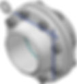
- Flushing ring
Flushing ring is used for flushing solution combined with diaphragm seals. This type of flushing ring is clamped between process nozzle and diaphragm seal. The flushing ring can be combined with the BF and BRF seal as well as the BC andBRC type. STANDARD EXECUTION BODY GASKET SURFACE FINISH FACING TYPE AISI 316(L) Ra 3.2-6.3 µm RF type B1 FLUSH CONNECTION 1/4”NPT FLANGED PROCESS CONNECTIONS FLUSHING CONNECTIONS, BODY MATERIALS,AND FACING OPTIONS Flush rings
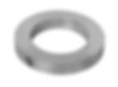
- The sealing ring of large flange replacement mode
The sealing ring is two pieces of large flanges are mutually connected, put in two pieces of flange sealing surface of the two and then tightened the bolt flange, the flange leakage of a product does not occur. In the large flange sealing ring to facilitate change when the seals need to be replaced, without dismantling the valve flap, just next to the flange valve fully open, then the took out the installation and operation of the key, after the operation mounted to the closed form still adhere to and the main valve linkage, then headed for open partial to the continued migration shift handwheel until the sealing ring is located in the valve body, sealing face seal side can be changed. Sealing ring of large flange in reverse bias stress task action, occurred from the sealing force, the sealing pressure to add, seal compression valve seat ring and reverse bias greater work pressure, self sealing force greater, so that sealing ring and the valve seat joint strict, reach the two-way sealing effect. In high pressure equipment and piping, adopt metal gasket lens type copper, aluminum, steel, 10 stainless steel or other shapes. High pressure gasket and sealing surface of the contact width is very narrow (line contact), high brightness light processing and gasket sealing surface. The flange (wire) connection points thread flange and welding flange. Low voltage and small diameter wire flange, high pressure and low pressure large diameter is used welding flange, different pressure thickness and cohesion bolt flange diameter and number is different. Grade according to pressure differences, there are differences between the flange gasket material, from the low pressure high pressure asbestos asbestos pad, pad to the metal pads are. The classified material of carbon steel, cast steel, alloy steel, stainless steel, copper, plastic, Aluminum Alloy, argon Ge Lek, PPC etc.. The manufacturing method can be pided into pushing, forging, forging, depressed. As long as the common welded flange flange ring, usually take steel manufacturing needs can be taken when rolling forging. In the convergence directly linked with the cylinder head or fillet welding. Large flange sealing valve rigid good, is not easy to deform DN300 more than the butterfly valve for the double plate truss flow structure, small flow resistance, good rigidity, in reverse bias stress task and not easy to deform, sealing ring can not follow the valve deformation and leave the seat the best seal point, thus ensuring the sealing ring for sealing.